FireGFX is a software platform which connects to Fire Alarm Control panels from multiple manufacturers and displays real-time alarm events on building plans.
To use the platform to monitor specific risks, a user must first 'Build A Site'
The term 'Build A Site' refers to importing specific building plans into the FireGFX software, linking the plans through zoomable views and populating the plan with Fire Alarm Devices.
For those that have created sites in other fire alarm graphics applications, the process should be straightforward, and this article will reference FireGFX specifics. For users new to working with Fire Alarm Graphics software applications, this article provides a step-by-step guide to building a complete site.
Downloading & Installing FireGFX
To start building a graphics site, the developer edition of the FireGFX software should be installed.
The Windows 10+11 unified installer for FireGFX can be downloaded as a 14-day free trial from here.
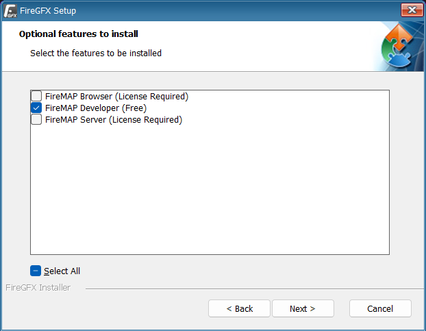
To install the software, run the installer and when prompted for which features to install, choose 'FireMAP Developer'.
Once installed, the software can be launched from the desktop shortcut or the Windows start menu.
If the software is unlicensed, you will be prompted to start a 14-day free trial.
Creating A New Site
Once running, a new site can be created by selecting 'File > New Site' from the main menu.
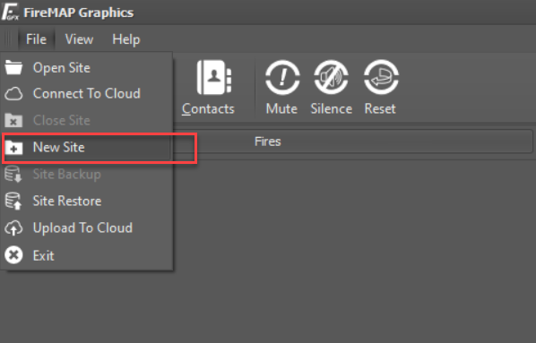
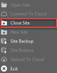
If the 'New Site' option is unavailable, ensure that the correct software version is running, IE., the developer edition. If the 'New Site' option is present but is not accessible, likely, an existing site is already open. Multiple sites can be created with the developer edition, so choose 'File > Close Site' first if this is the case.
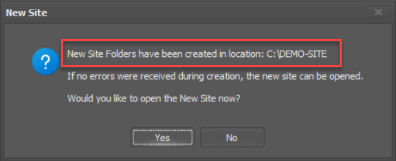
After selecting the 'New Site' option, a dialogue box will ask for a site name. The site name should be meaningful and generally related to the name of the protected building, site or client. For demonstration purposes, entering a name such as 'Demo-Site' here will suffice. The site name will be restricted to valid characters, in uppercase, by the software.
Once a new site is created, a cache folder will be created on the local C:\ drive with the site's name entered above. The local folder can be used to open this particular site in the future. For now, you will be prompted to open the newly created site for editing. Click 'Yes' to open the site.
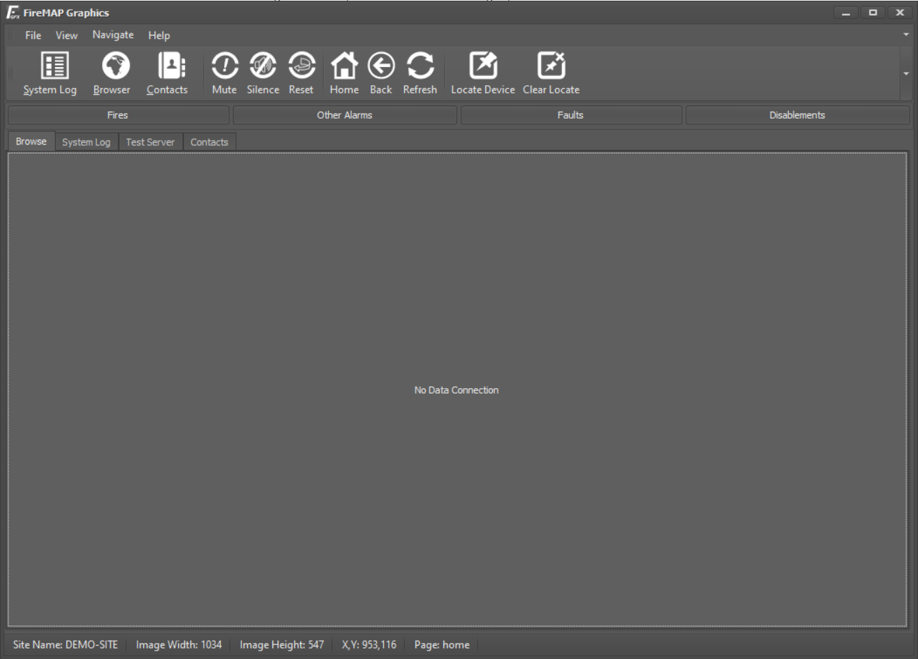
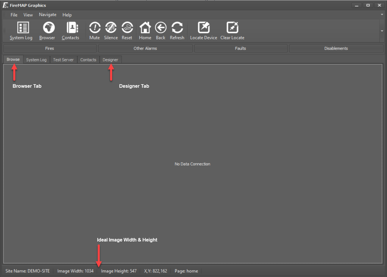
The main application will launch into the Graphics Browser window. The site does not yet contain maps and will be blank with a data connection warning.
Building The New Site
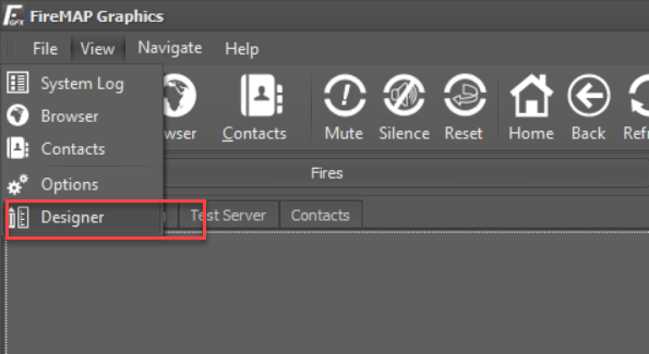
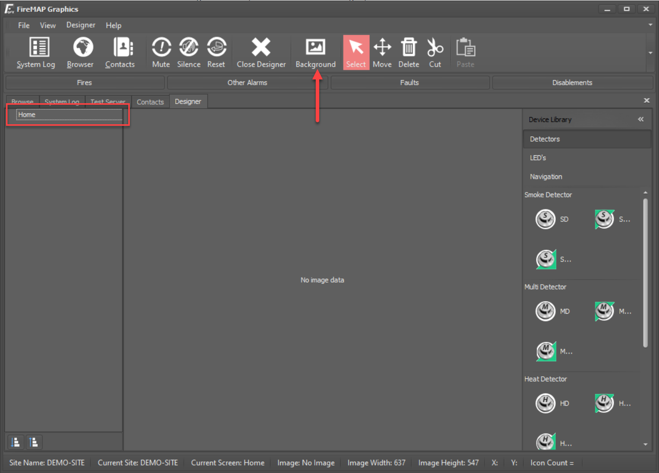
To begin designing a new site, choose 'View -> Designer' from the main menu.
The designer will launch which is split into three main parts:
- The Site Navigator
- The Map Window
- The Device Library
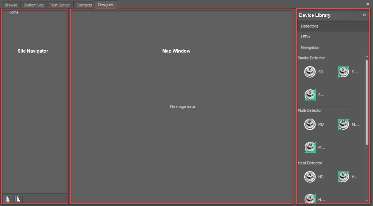
The button bar at the top of the screen also changes to provide additional tools for working with maps and icons.
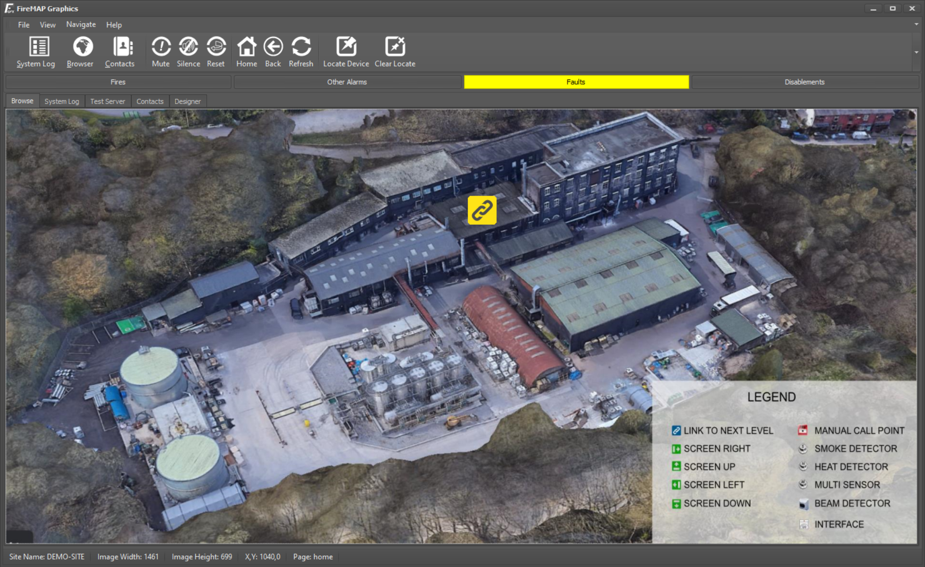
To begin a 'Site Build', the first background map must be imported. The first map screen name defaults to 'Home' and is generally an overview of the site if multiple buildings are being added or a side elevation of a building if only a single building is being covered.
Background maps are simply bitmap images in '.JPG' (jpeg) format, usually exported from CAD drawings. The image size depends upon the screen resolution used but will automatically scale for different size devices.
To find the ideal size for the current screen resolution, a user can click the 'Browser' tab, check the status bar and note the image size, and then click the 'Designer' tab to return to the designer.
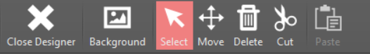
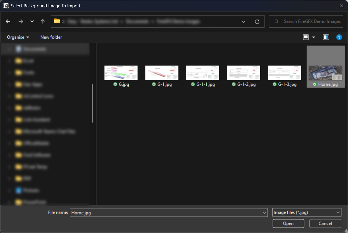
To import a background image, ensure that the current screen is selected in the navigator (Home in the first instance) and then click the 'Background' button in the toolbar.
A standard Microsoft Windows file menu will open, enabling a user to select a pre-prepared file for the background of the 'Home' screen. Choose the correct image and click 'Open'.
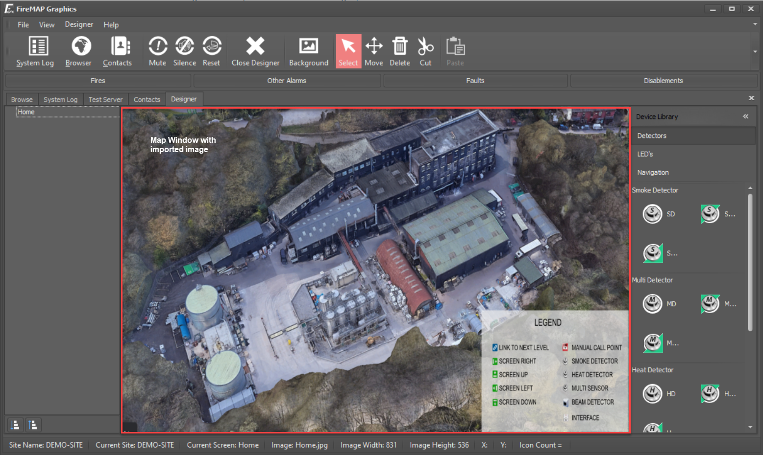
The Map window will display the 'Home' screen with the selected background image.
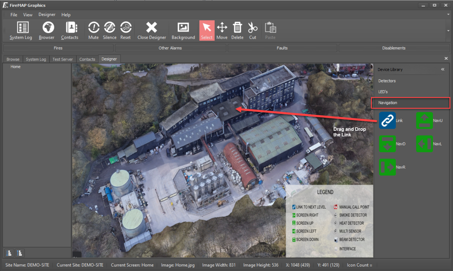
The next step in the 'Site Build' process is to add a link to the 'Home' screen, which will zoom to a specific building on a site plan or a specific floor level on a side elevation.
Adding a zoom link will create a new 'Branch' on the site navigation tree directly under the screen that it is placed upon. In our example above, we'll add a link on the 'Home' screen linking to the office building and name the link 'Office'. Providing a meaningful name for the link aids in navigating through large sites at a later date.
To add a link, select the 'Navigation' tab in the Tool Box window, drag a 'Blue' zoom link from the Tool Box and drop it onto the area in the image where the office is located. Once the link is dropped, a dialogue will appear to provide the name of the link. In our example, we'll enter the name 'office' into the dialogue and click 'OK'
Once the link is dropped, the new branch, called 'Office', appears in the site navigation window. A user can navigate between the two pages on the site by clicking the appropriate branch name in the site navigation tree.
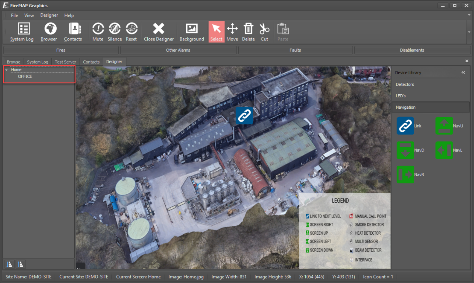
Selecting the 'Home' branch will display the home screen with the imported background image. Selecting the 'Office' branch will display the office screen, which currently has no background image.
To assign a background image to the 'Office' screen, repeat the steps above. Select the 'Office' branch in the site navigation window, click the background button in the toolbar, select a pre-prepared background image for the office and click 'open'.
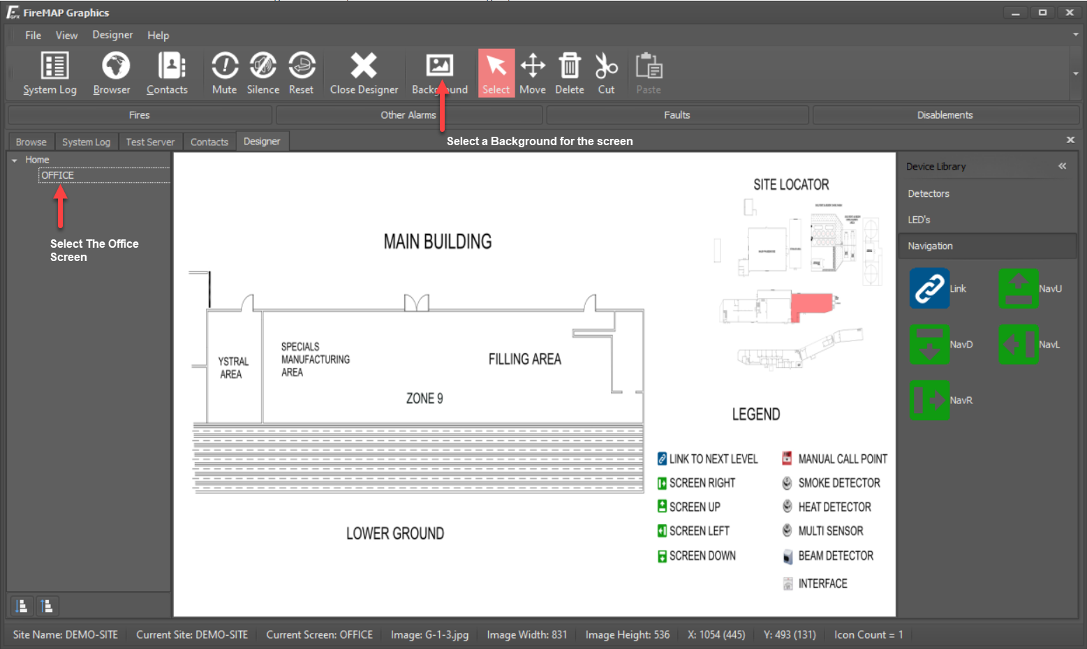
The site now contains two screens with backgrounds. At this point, navigating the site tree between the 'Home' and 'Office' branches will display the screens with their backgrounds.
To test the 'Site Build', click the 'Browser' tab. The 'Home' screen containing the zoom link will be displayed as an end user sees it. Click the zoom link to zoom into the 'Office' screen. Click the 'Back' button in the browser toolbar or the 'Home' button to navigate back to the 'Home' screen.
The screens, maps and links are automatically saved. If the application is shut down at this point and this site is re-opened, the site build will be intact.
Additional screens and links can be added as above by navigating back to the 'Designer' tab and dragging and dropping links from the 'Navigation' toolbox onto any of the screens.
Up to ten zoom levels plus the home screen can be created, which is enough to zoom from a map of the world to a country, to a city, to a site plan, to a building elevation, to a building level floor plan down to five additional zoom levels of that particular floor plan!
Inserting devices
Adding devices to the screens is as straightforward as adding links. In the site navigator window of the designer, select the 'Office' branch to display the office background image. In the Tool Box, select the 'Detectors' tab to display the detector library.
To add a device, locate the device type to add, IE, Smoke Detector, Heat Detector etc., in the Tool Box, drag it onto the background image and drop it into the required location.
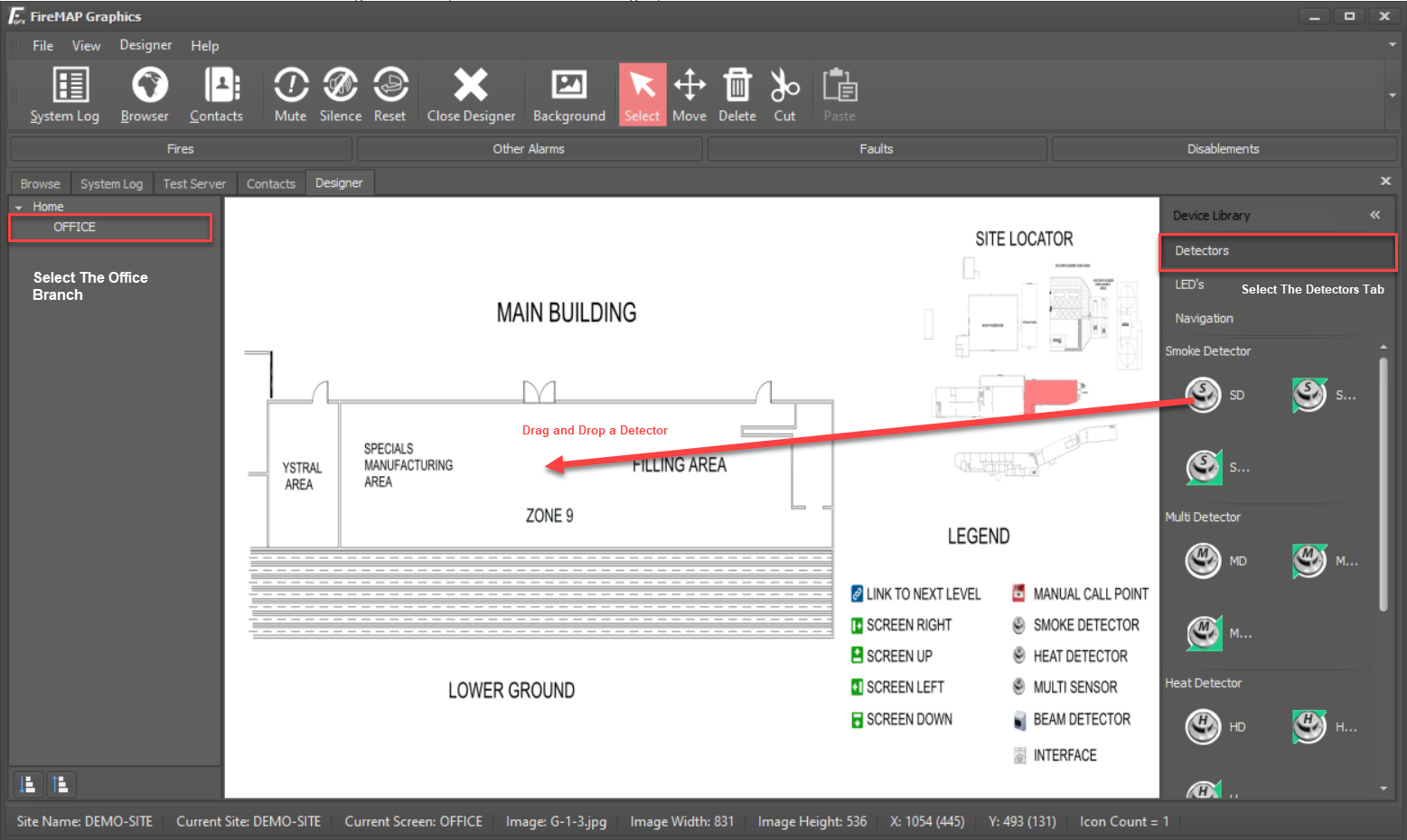
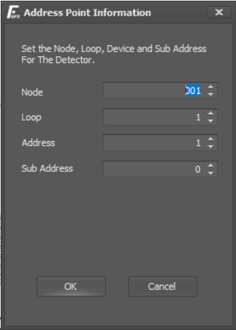
Once dropped, the device attribute dialogue box will open where the Node, Loop, Device and Sub-Address numbers can be entered. Enter the relevant address information for the device or accept the defaults and click 'OK' to place the device. The device Address number will automatically increment for each additional device added, making placement of sequentially addressed devices quick and easy.
Repeat the above for all devices on the current floor plan. Use the site navigation window to switch between screens and continue dragging and dropping devices to any additional screen where required.
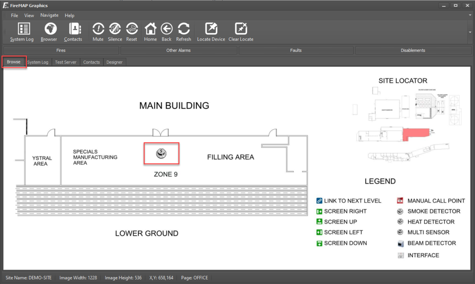
To validate the site build, click the 'Browser' tab to switch to the browser view and navigate the site by clicking the links to each floor plan. Any devices added to the designer will be visible on the relevant floor plans.
Testing the Site Build
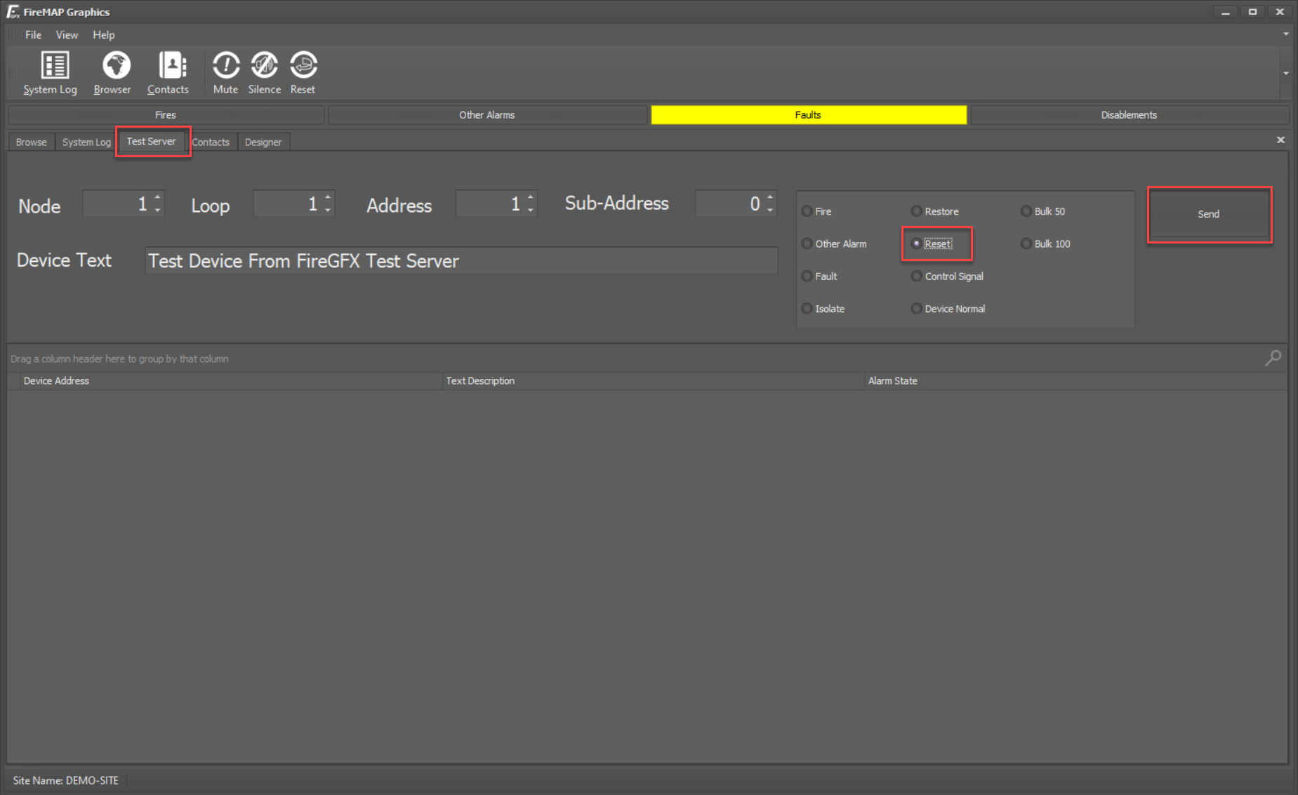
The devices can be further tested using the 'Test Server' tab.
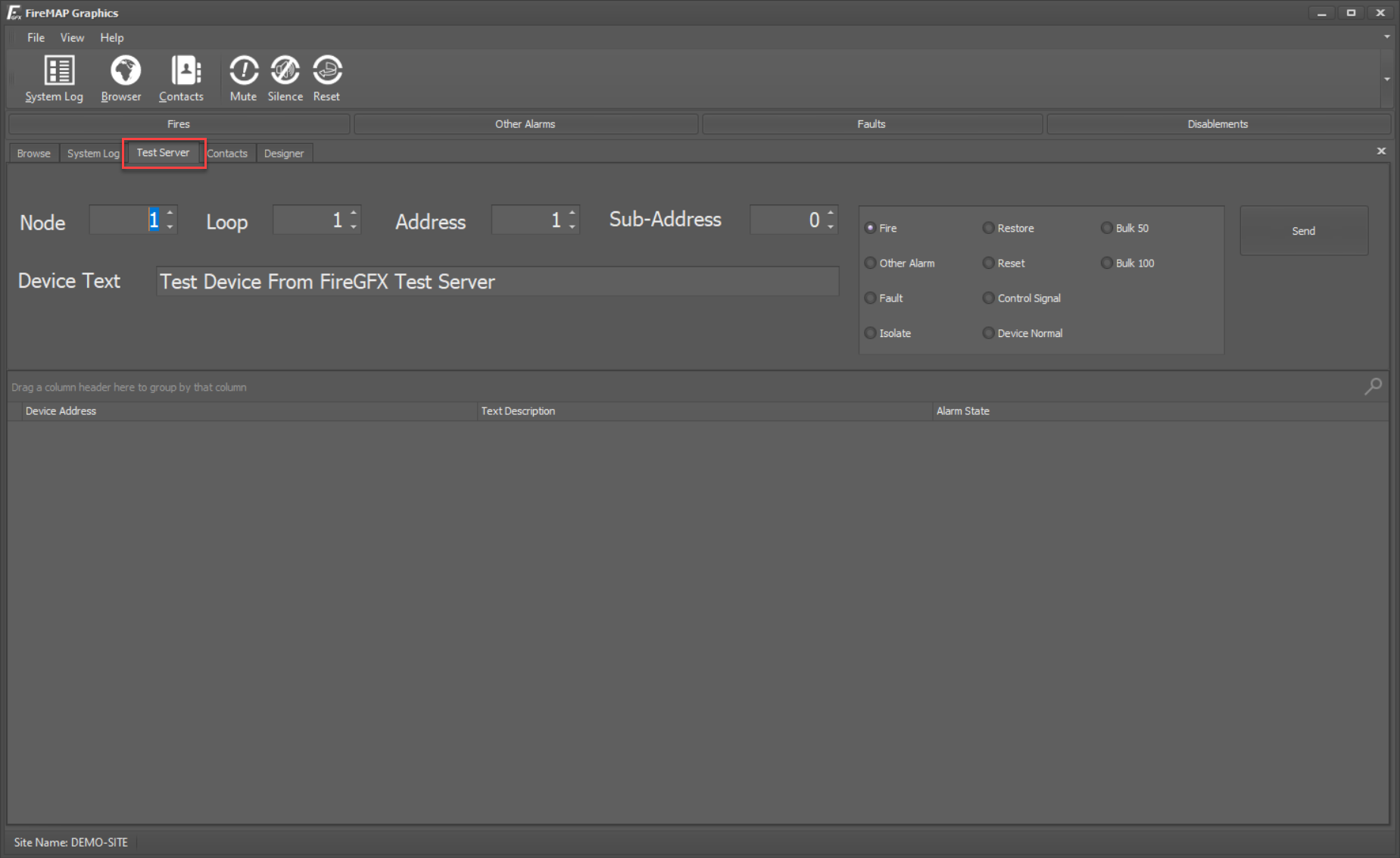
In our example above, we only added one device, which was the address: Node 1, Loop 1, Address 1, Sub-Address Zero. Set the corresponding address information in the Node, Loop, Address and Sub-Address boxes. The device text box has a message that can be changed and generally corresponds to the device text programmed into a fire panel. For test purposes, the device text can be anything; it will simply be logged as if it had been sent from a panel. Select an alarm condition in the command box to the right of the address information. For this example, we'll select 'Fault', which will generate a detector fault. Finally, click the send button to transmit the command.
Once the test alarm has been sent, click the 'Browser' tab and the 'Home' button. The graphics browser will display the Home page with the zoom links flashing in yellow to indicate that a fault is active in the 'Office' building.
Click the link to zoom into the 'Office Building'. The smoke detector added in our example above is now flashing with a yellow warning triangle to indicate that it is the device in alarm.
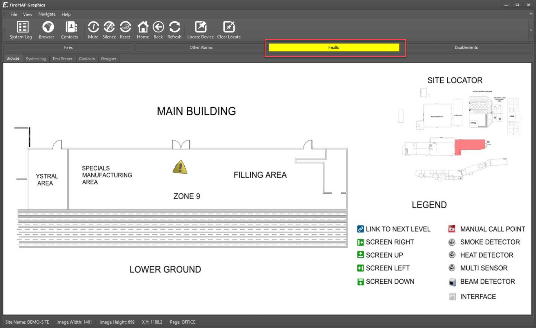
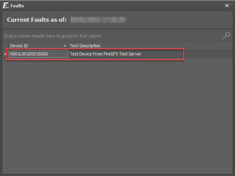
Clicking the Yellow 'Fault' bar will display a list of current fault conditions. The fault identifies that Node 1, Loop 1, Address 1, and Sub-Address Zero with the pre-programmed text message is currently in fault.
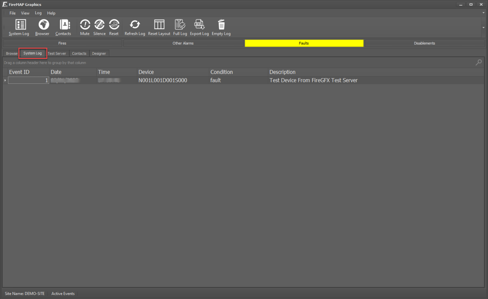
Selecting the 'System Log' tab displays the historical log. The historical log records and saves all system events for later analysis. It is different to the Fault List above. Once a device returns to normal, it will be removed from the current fault list but remain as a historical event in the system log.
To reset the alarm condition, switch back to the 'Test Server' tab, select the 'Reset' command in the command options and click 'Send'
Finishing Up
Once a site has been completed, it can be closed to allow additional sites to be created. To close a site, choose 'File > Close Site'.
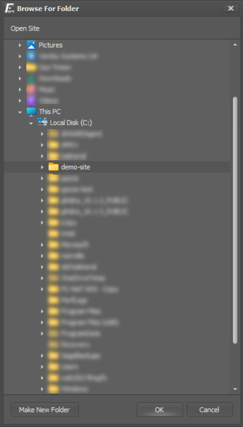
To re-open the demo site, choose 'File > Open Site' and navigate to the 'C:\DEMO-SITE' folder on the local PC. Clicking OK will re-open the demo site.
Once a site has been opened using the 'File > Open Site' command, it will be remembered by the FireGFX software and automatically opened each time the software is run.


SHARE